
|
|
|
|
|
|
I revised the blast door setup yet again, in an attempt to make it even simpler. Trying to synchronize two servos at varying speeds proved more difficult than I thought, and produced inconsistent results at best. So I have returned to using just one servo, and having it control both rollers. Since I already have one servo connected directly to the smaller roller, I will just need to add a small pulley to it, and a long o-ring to attach the larger roller. The speed difference will be accounted for in the pulley sizes.
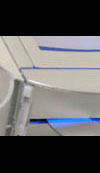
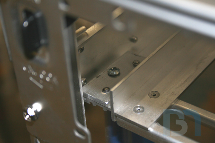
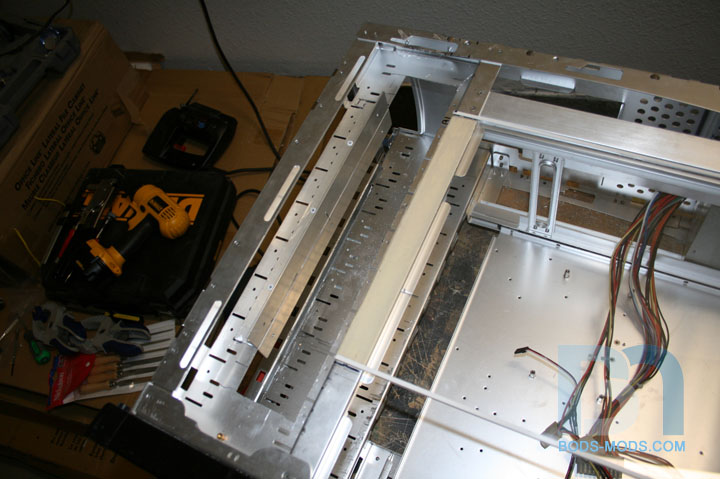
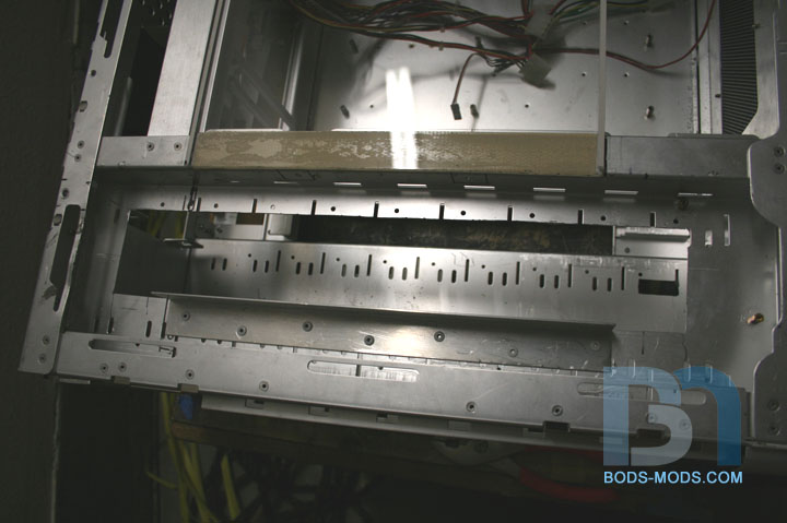
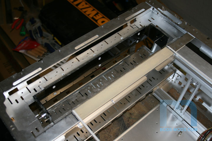
Another alteration is to simplify the path that the door has to take. I had originally intended for the door to travel towards the front, and make a 90° turn into the hard drive cage where the rollers were located. That was adding too much drag, and the door was getting caught up at the turn. So my solution is to hack away part of the hard drive cage and mount the roller closer to the window, thus shortening the path. After cutting away part of the hard drive cage, I took two pieces of aluminum angle bar and sandwiched them together, with the HD cage in the middle. Using pop rivets in a staggered fashion, I fastened them together. This will provide a good solid mount for the cut-down roller holder. Then I pop-riveted the holder into place, utilizing the holes I drilled prior to riveting down the angle pieces. Once I get the second roller in place, I can measure the distance between the two and see how large an o-ring or belt I will need.
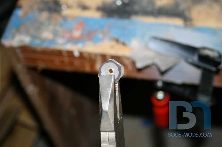
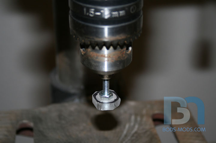
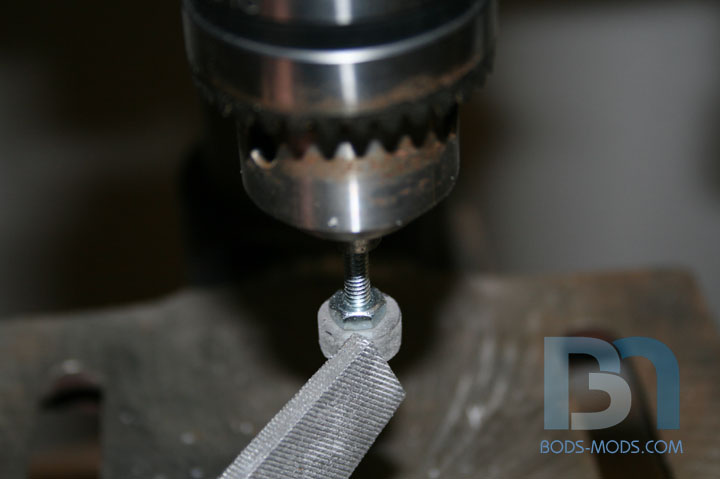
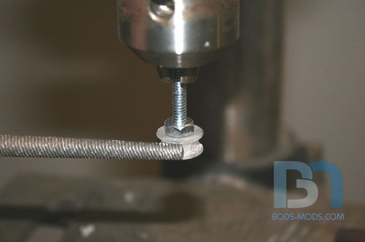
Worked on making a small pulley for the small roller last night. I measured out a circle about 1/2" diameter on 1/4" thick acrylic and cut it out. I stuck a bolt through it, then using the ol' drill press, I proceeded to file it down to size. This makes a perfect circle. Then I made the channel of the pulley with a round file. Next up, gluing it to the roller, and adjusting the servo mount.
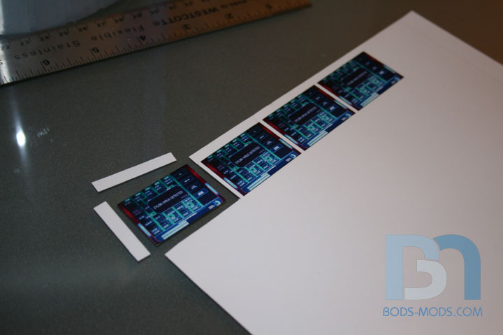
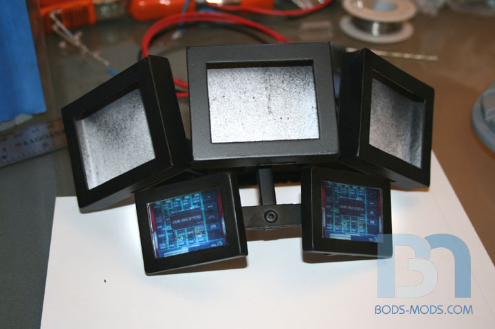
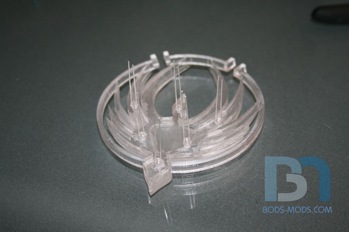
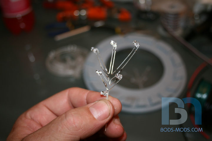
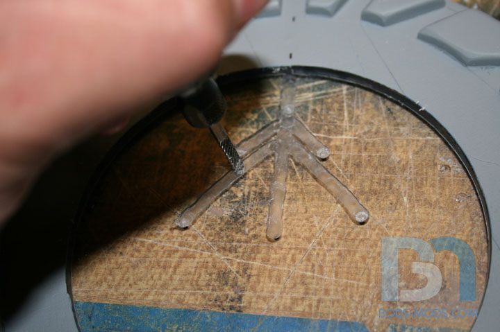
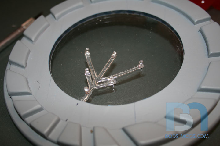
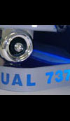
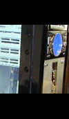
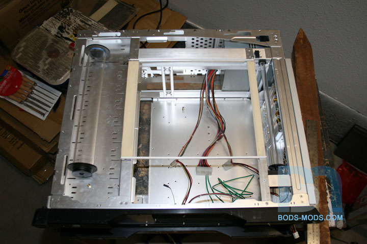
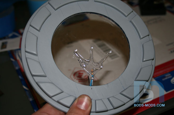
Moving right along, I'm getting things wired up. Starting with some led strings, one for the dummy lcd screens in the cluster, and another for backlighting the medallion. First, I printed some BSG graphics onto transparency paper and cut them out. This particular transparency paper has an adhesive backing. Stuck them onto the screens. These leds will be white. I forgot to take a picture of the leds wired up and in place behind the screens. I will post that and a shot of it all lit up this weekend. For the medallion, I drilled six holes behind the bird to fit the leds. These will be red. Then I soldered them all together in series. For the medallion base, I routed out some material to make room for the wiring. This will all be hidden behind the bird, which will be painted. Here's a shot of the leds placed in the routed area. I drilled a hole through the base at the bottom for the wires to feed through. Once I get it all soldered together and tested, I will use some hot glue to keep everything in place, then sandwich it all together. Then I can paint it!
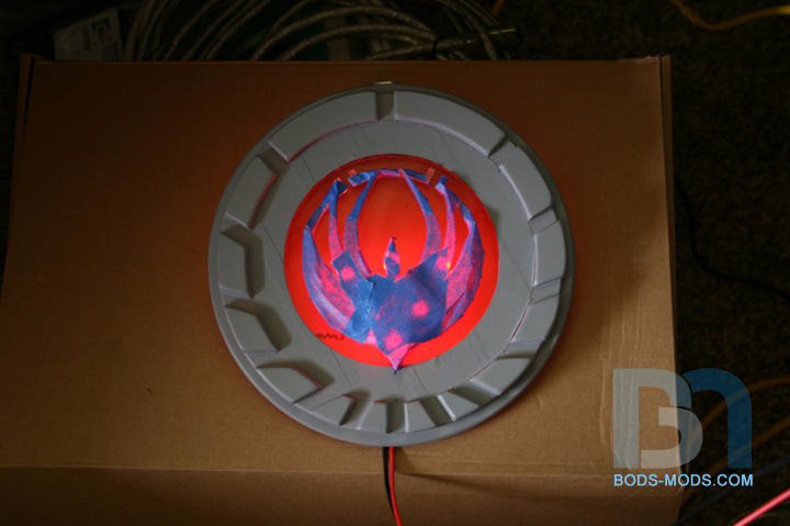

I've been working more on the led strings, and did some testing. I decided to do all six led's in series, with a 10ohm resistor. Since I haven't painted the bird yet, I threw some masking tape over it to give you kind of an idea of how it will look with the backlight. So disregard the faint bleed through! Although it does show you where the leds are.
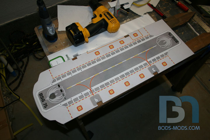
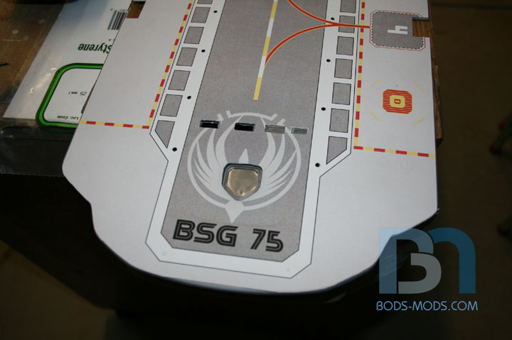
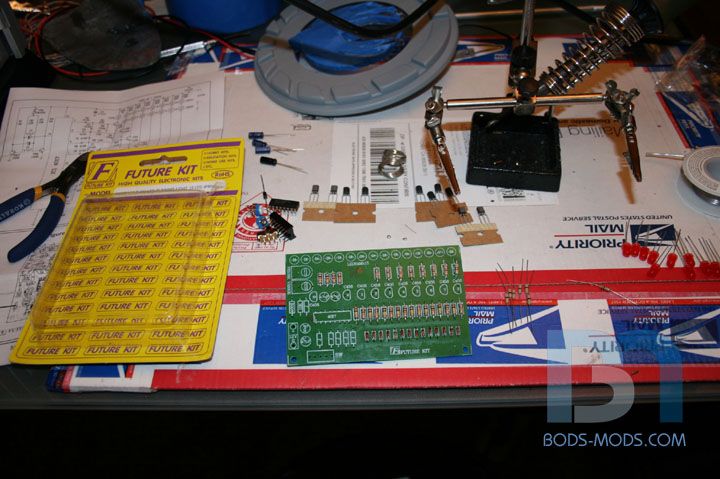
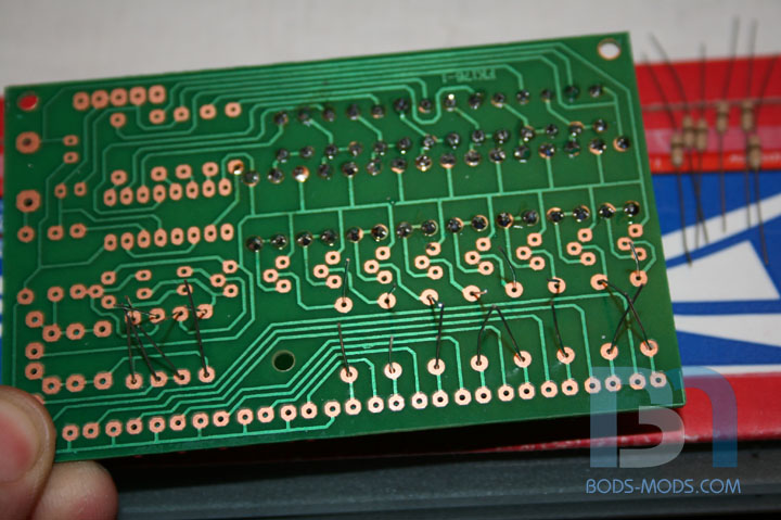
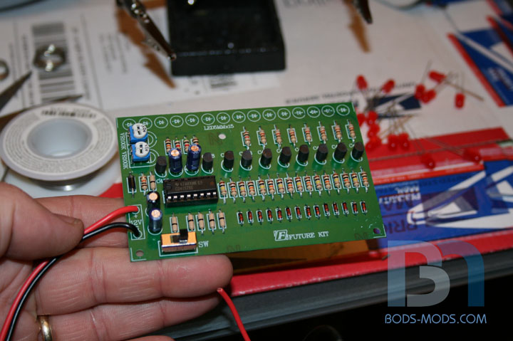

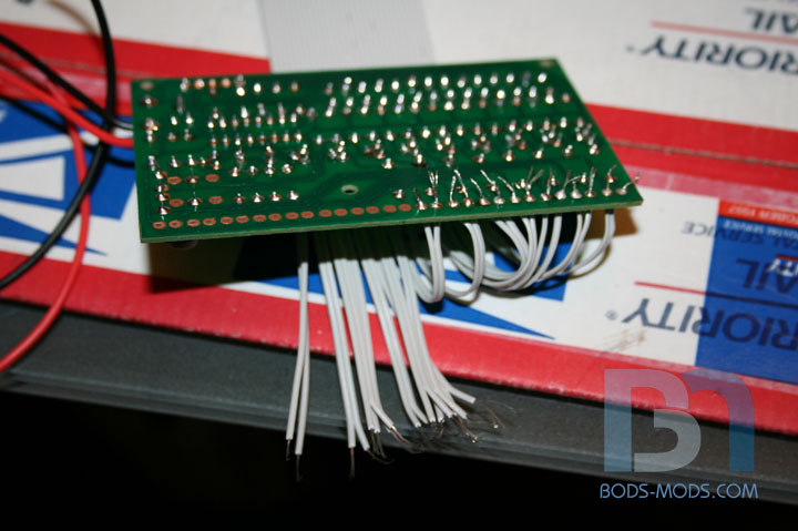

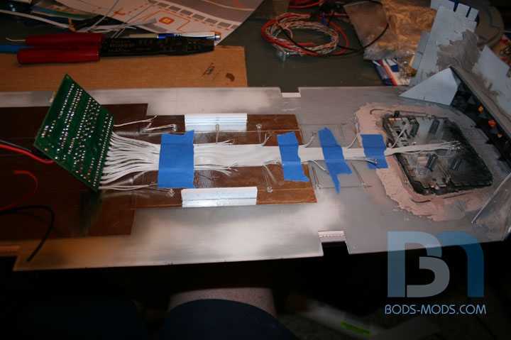
I've been working on more led's. This time I'm wiring up the running lights that will blink sequentially on the landing deck. Now I'm no electronics guru, I think I've mentioned that before. About all I'm good for is determining positive from negative, and basic soldering. :P So since I can't make up a custom circuit that will make the led's blink in sort of sequence, I found one online! Qkits sells these led kits in many forms. This one in particular has 15 leds in a row that blink sequentially from the center out. The kit is really quite simple, it just requires you to solder all the components onto the circuit board. After about an hour of soldering, I got all the pieces mounted, with the exception of the leds. I will be replacing the red 5mm ones with white 3mm leds. The resistors in the kit should make them a bit dimmer, but thats ok. Now obviously, I won't be soldering the leds onto the circuit board, as they have to be relocated to their respective places on the landing deck. To accomplish this, I will be using a spare floppy drive ribbon cable. It has 34 wires, but I only need 30. So I simply slice off the remaining 4. I soldered one end to the kit's pcb where the led's would have gone. Now with the led's in place, I can cut the individual wires to length and solde them up. This kit has 15 leds, and runs the lights from the center out. So I will be putting the first led up front under the power button, then the rest down both sides so it will blink in pairs into the landing bay. I also made some rails out of styrene to hold the pcb underneath the landing deck. You can see them in the last pic. Hopefully I can finish this thing up tonight and do a test run.